FANUC Alarm 414 Servo Alarm – Causes and Repair Solutions
Overview
FANUC Alarm 414 (Servo Alarm) indicates a servo system abnormality detected by the CNC controller. This alarm typically prevents axis movement and stops machine operation until the issue is resolved.
The alarm is commonly associated with current detection errors, amplifier faults, encoder feedback issues, or motor-related electrical problems.
Common Symptoms
414 SERVO ALARM: X-AXIS DETECTION RELATED ERROR
Main Causes of FANUC Alarm 414
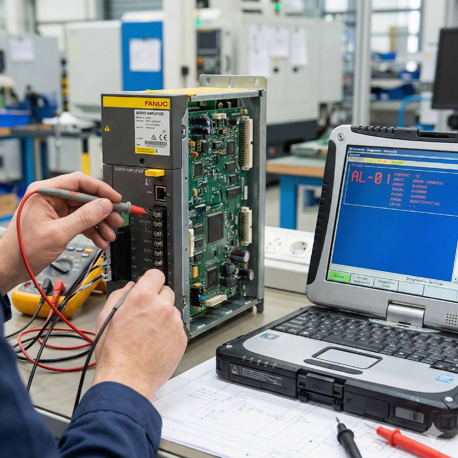
1. Servo Amplifier Failure
Internal circuit failure, overcurrent condition, or damaged IGBT modules.
2. Servo Motor Electrical Fault
Short circuit between motor phases or insulation breakdown to ground.
3. Encoder or Feedback Cable Issues
Loose connector, damaged cable shielding, or electrical noise interference.
4. Power Supply Instability
Low voltage or unstable incoming power to the servo amplifier.
5. Incorrect Servo Parameters
Improper parameter configuration after replacement or maintenance.
Step-by-Step Diagnostic Procedure
Step 1 – Identify the Affected Axis
Confirm which axis triggered the alarm from the CNC screen.
Step 2 – Inspect Servo Amplifier LEDs
Check the servo amplifier status indicators:
Refer to the specific FANUC amplifier manual for LED code definitions.
Step 3 – Motor Isolation Test
Power off the machine.
Disconnect the motor power cable and encoder feedback cable from the amplifier.
Power on the system:
Step 4 – Motor Electrical Test
Use a multimeter or insulation tester to check:
Step 5 – Parameter Verification
After replacing any hardware:
Practical Maintenance Recommendations
Conclusion
FANUC Alarm 414 is primarily related to servo current detection or feedback abnormalities. A structured diagnostic process—starting from the amplifier and moving toward the motor and cabling—usually leads to accurate fault isolation and repair.
Proper preventive maintenance significantly reduces recurrence.